- Height: 1.4 meters
- Weight: 50kg

Quick Start
KESTREL System - Overview and Specs
The KESTREL system provides the user with airspace awareness by providing both active and passive aircraft detection methods.
Some versions also include a tracking camera.
- NEST The NEST serves as the support box for the KESTREL, providing power and data to the various sensors.
- Weight: 5kg
- Power: 110v
- Tripod:System can be mounted on any 1.5 inch diameter tube
- Tube Diameter: 1.5 inch / 38mm
- SEN-IDSEN-ID sensor passively detects RF from cooperative aircraft. This sensor receives remote ID and ADS-B information.
- Sensor type: Passive RF Detection
- Frequencies: ISM
- Range (rural environment): Up to 25km
- Range (urban environment): Up to 10 km
- Antenna type:
- Omnidirectional, 10Mhz - 6Ghz
- Remote ID detection
- AIS detection
- Mode S detection
- ADS-B detection
- GPS
- Internal memory: 1TB
- Connectivity: LAN
- Dimensions: 310mm x 310mm x 100mm
- Weight: 2.4kg/5.3 lbs
- Temperatures: -40C to 120C
- Ingress Protection Level: IP 67
- Power Consumption: 100 W
- Echodyne / Echoguard Radar PanelUp to 4 radar panels may be used.
- Instrumented Range: 6 km
- Range
- sUAV (Phantom 4): > 1 km
- sUAV (Matrice 600): > 1.4 km
- Vehicle: > 3.5 km
- Human: > 2.2
- Field of view: km 120° azimuth x 80° elevation
- Angular resolution: 2° azimuth x 6° elevation
- Maximum tracks: Up to 20 simultaneous tracks
- Size: 20.3 cm x 16.3 cm x 4 cm
- Weight: 1.25 kg (2.75 lbs)
- Power required: DC +15 V to +28 V (US)
- Power consumption:
- Operating: < 50 W
- Hot standby: < 8 W
- Power I/O: Snap lock 12 pin connector
- Operating temp:p -40°C to +75°C
- Weather Protection: IP67 Integration
- Control I/O: Gigabit Ethernet
- Data output:
- R/Vmaps: 40 MB/s
- Detections: 1 MB/s
- Measurements: 1 MB/s
- Tracks: 25 kB/s
- Mounting: VESA 75 & 100 mm
- SEN-HUBSEN-HUB collects and processes data, steering a camera to give the user live video of targets.
- Power: 110v - 20 Amps
- Operating temperature: -40C to 70C
- Dimensions: 310mm x 310mm x 100mm
- Weight: 2.4kg/5.3 lbs
- Axis Communications Q6225-LE 2MP Outdoor PTZ Network Camera with Night Vision & Wiper (60 Hz)Tracking Camera is steered by SEN-HUB using collected sensor data.
- Image sensor: 1/2" CMOS
- Focal length: 6.9 to 214.6mm
- Field of view:
- Horizontal: 63.8 to 2.2°
- Vertical: 37 to 1.3°
- Pan/Tilt (programmed):
- Pan: 360° at 150°/s
- Tilt: 180° (-90 to 90°) at 150°/s
- Sensor resolution (Effective): 2 Megapixel
- Minimum illumination:
- Color: 0.05 lux
- Black and white: 0 lux
- Zoom:
- Optical: 31x
- Digital: 12x
- FOV:
- Horizontal: 63.8 to 2.2 degrees
- Vertical: 37 to 1.3 degrees
- Max aperature: f/1.36 to 4.6
- Max IP streaming (via RJ45): 1920 x 1080 up to 60.00 fps
- Memory: 1024 MB RAM / 512 MB Flash
- Material of construction: Aluminum
- Ingress protection level: IP68
- Impact resistance: IK10
- Operating conditions: -58F to 131F/-50C to 55C at 10 to 100% Humidity
- Startup temperature: -40F/-40C
- Storage conditions: -40F to 149F/-40C to 65C
- Illumination: 850 nm IR LEDs up to 1300'/396.2 m
- Dimensions:
- Width: 313mm/12.3"
- Height: 330mm/13"
- Depth: 210mm/8.3"
- Weight: 19.2lb/8.7kg
Hardware Assembly
Assembly. KESTREL hardware set up takes a few minutes and requires no tools.
- Position tripodPosition and secure the tripod in the desired location. Tripod should be level.
- Install sensor bracketSlide the sensor bracket onto the tripod
- Install radar/camera bracketInstall the radar/camera bracket onto the tripod. Tighten the thumbscrews enough to prevent the bracket from rotating.
- Install radar panel armsInstall the radar panel arms. Arms are installed and release by pressing a snap button.
- Install radar panelsInstall the radar panels and tighten the thumbscrews.
- Install SEN-ID/SEN-HUBInstall the SEN-ID. If a tracking camera is used, install the SEN-HUB as well and tighten all thumbscrews.
- Install SEN-ID antennasAttach the antennas for the SEN-ID in the proper order.
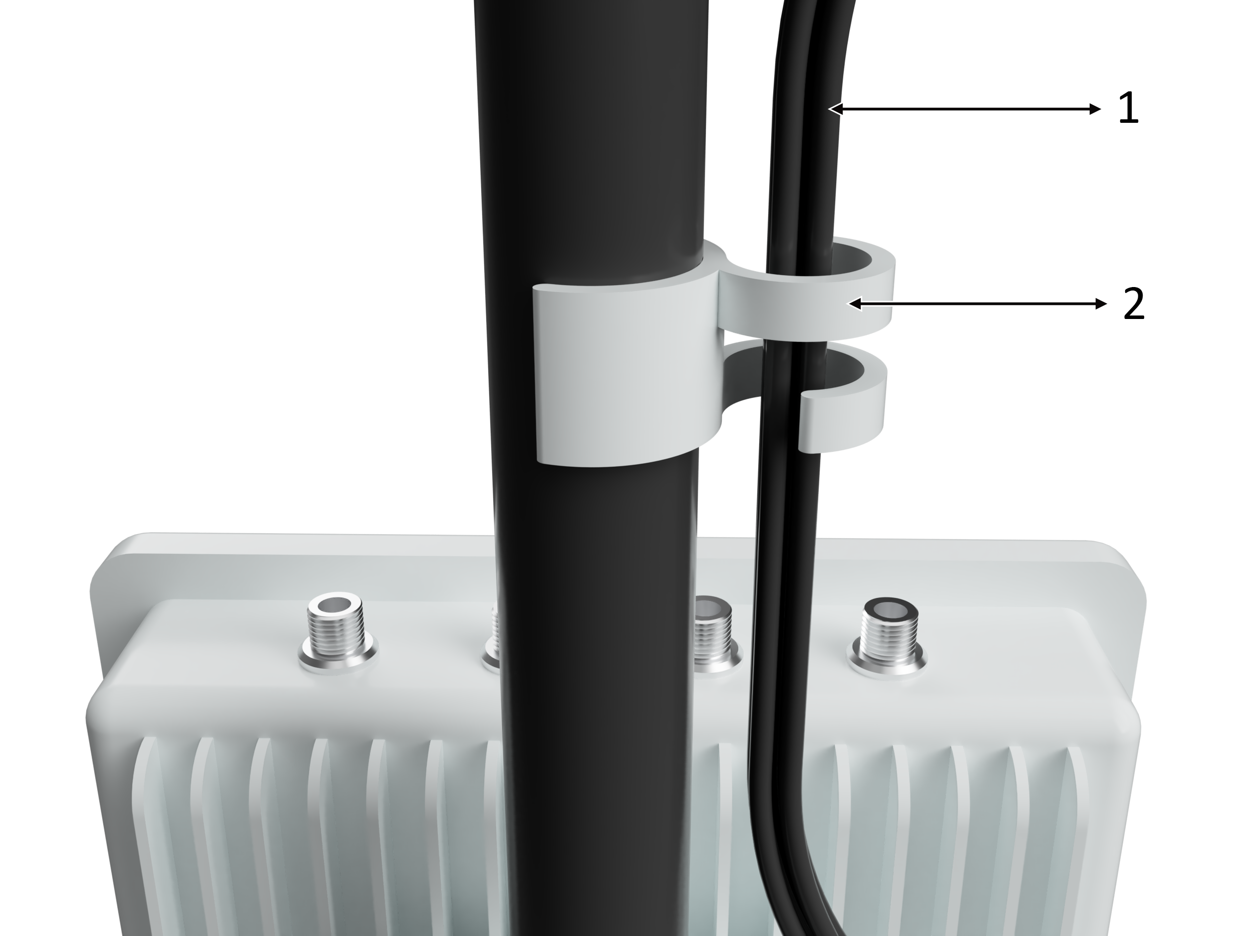
- Install cable clipLastly, attach the cable clip to the tripod and run all cables through.
Cable Connections - No Tracking Camera
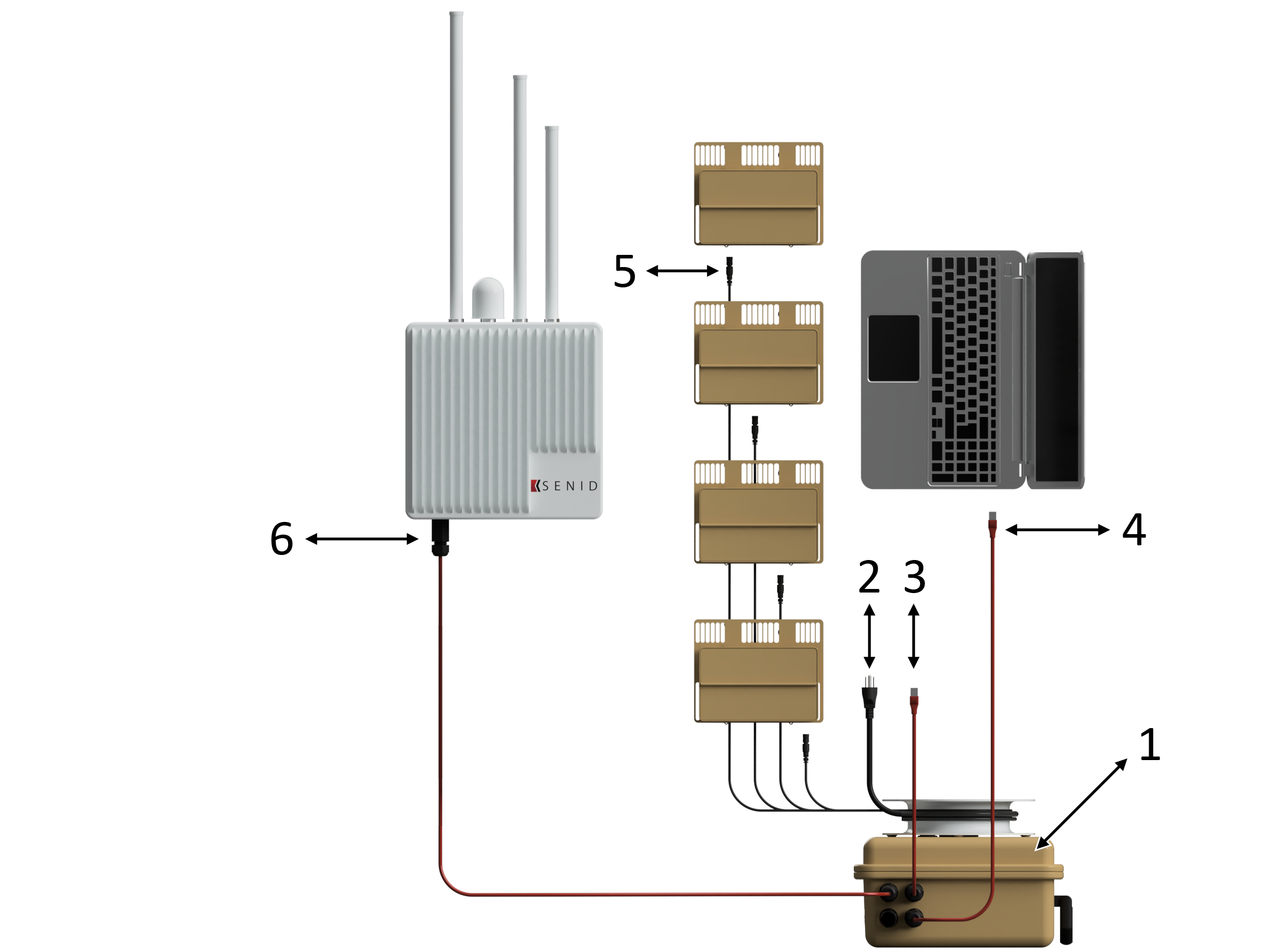
The KESTREL system may be used with or without a SEN-HUB and tracking camera. Follow this diagram for use without a SEN-HUB/tracking camera.
- Nest Connects to the SEN-ID, internet and the user computer by the three depicted ethernet ports.
- 110v Power Power is provided to the NEST through a 110v plug which is spooled around the NEST.
- Connection to the internet.
- Connection to the user computer.
- Radar Panels Connection to radar panels via radar cables which are spooled around the NEST.
- Connection to SEN-ID. (Port A)
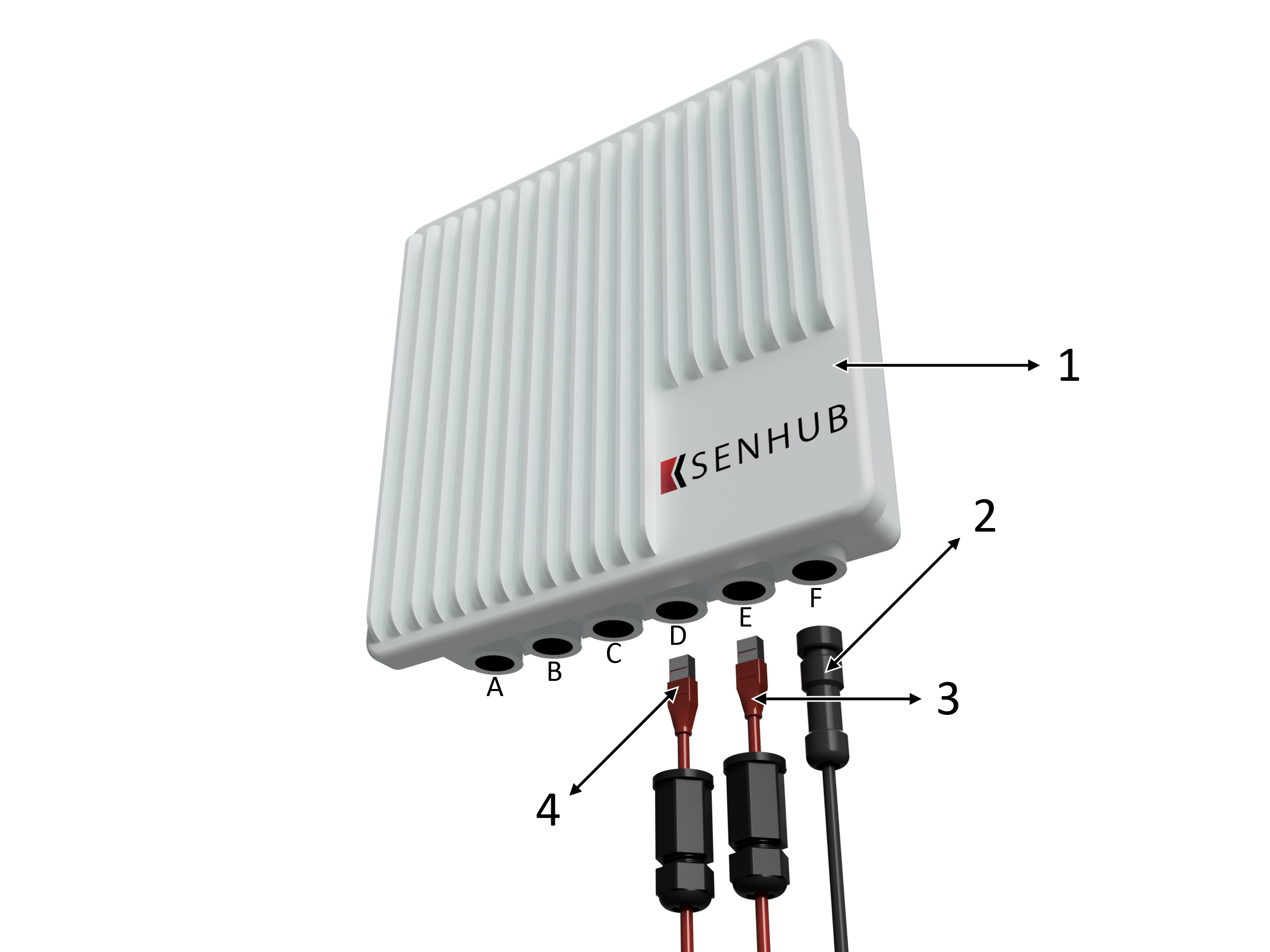
Cable Connections - With Tracking Camera
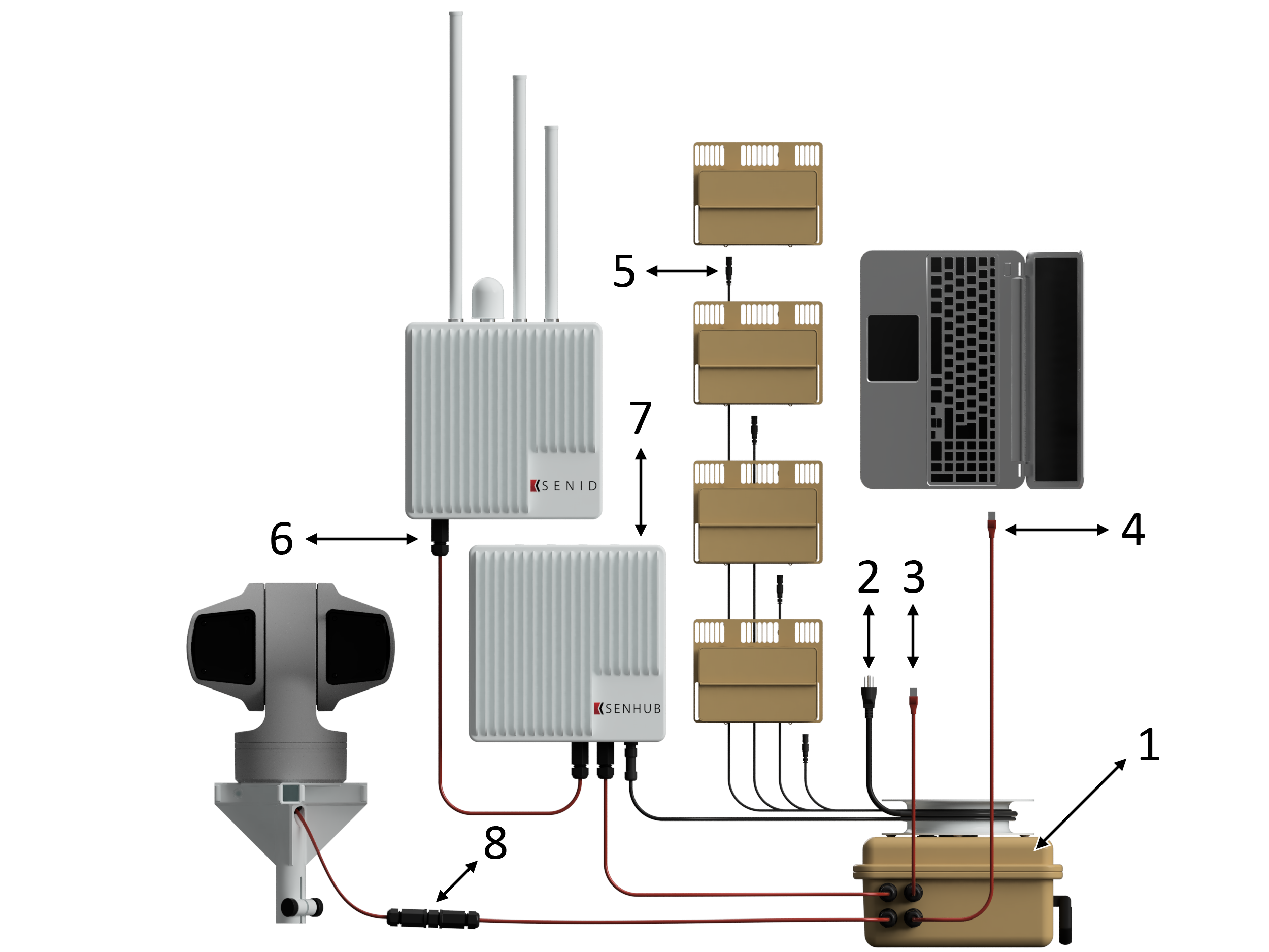
The KESTREL system may be used with or without a SEN-HUB and tracking camera. Follow this diagram if using the SEN-HUB/tracking camera.
- NESTConnects to the SEN-ID, internet and the user computer by the four depicted ethernet ports.
- 110v PowerPower is provided to the NEST through a 110v plug which is spooled around the NEST.
- Internet Connection
- User Computer
- Radar PanelsRadar panels are connected via radar cables which are spooled around the NEST.
- SEN-IDConnection to SEN-ID. (Port A)
- SEN-HUBThe (Port A), is connected to the NEST via the SEN-HUB (Port D and port E). Power is provided to the SEN-HUB through the SEN-HUB power cable (Port F), which is spooled around the NEST.
- Tracking CameraTracking camera is connected via ethernet cable to the NEST through port 3.
System Storage
Cases and Tripod
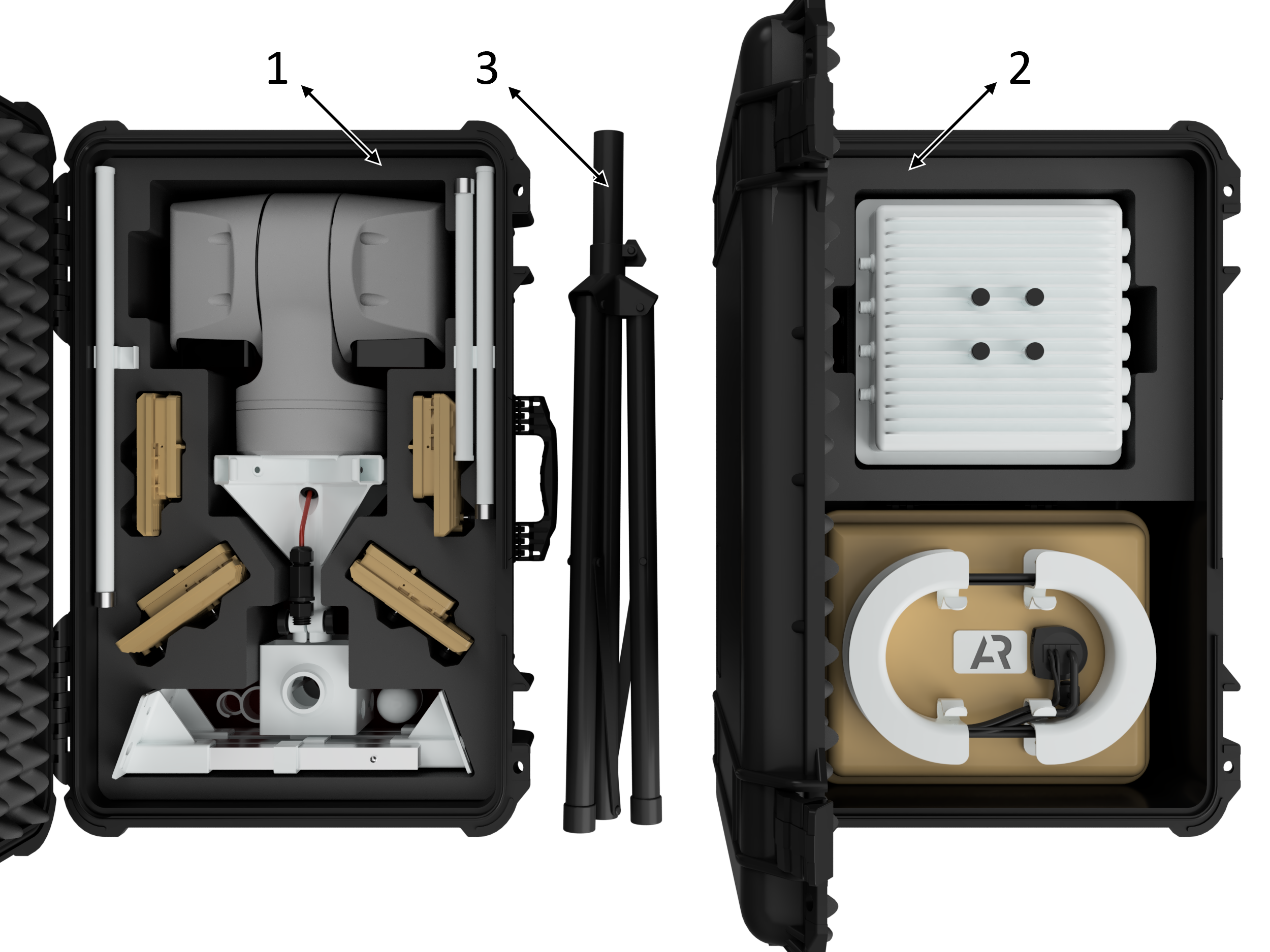
- Case 1Stores the radar panels, antennas, mounting brackets and the tracking camera if used.
- Case 2Stores the NEST, SEN-ID and SEN-HUB if a tracking camera is used.
- TripodTripod packs into a separate carrying case.
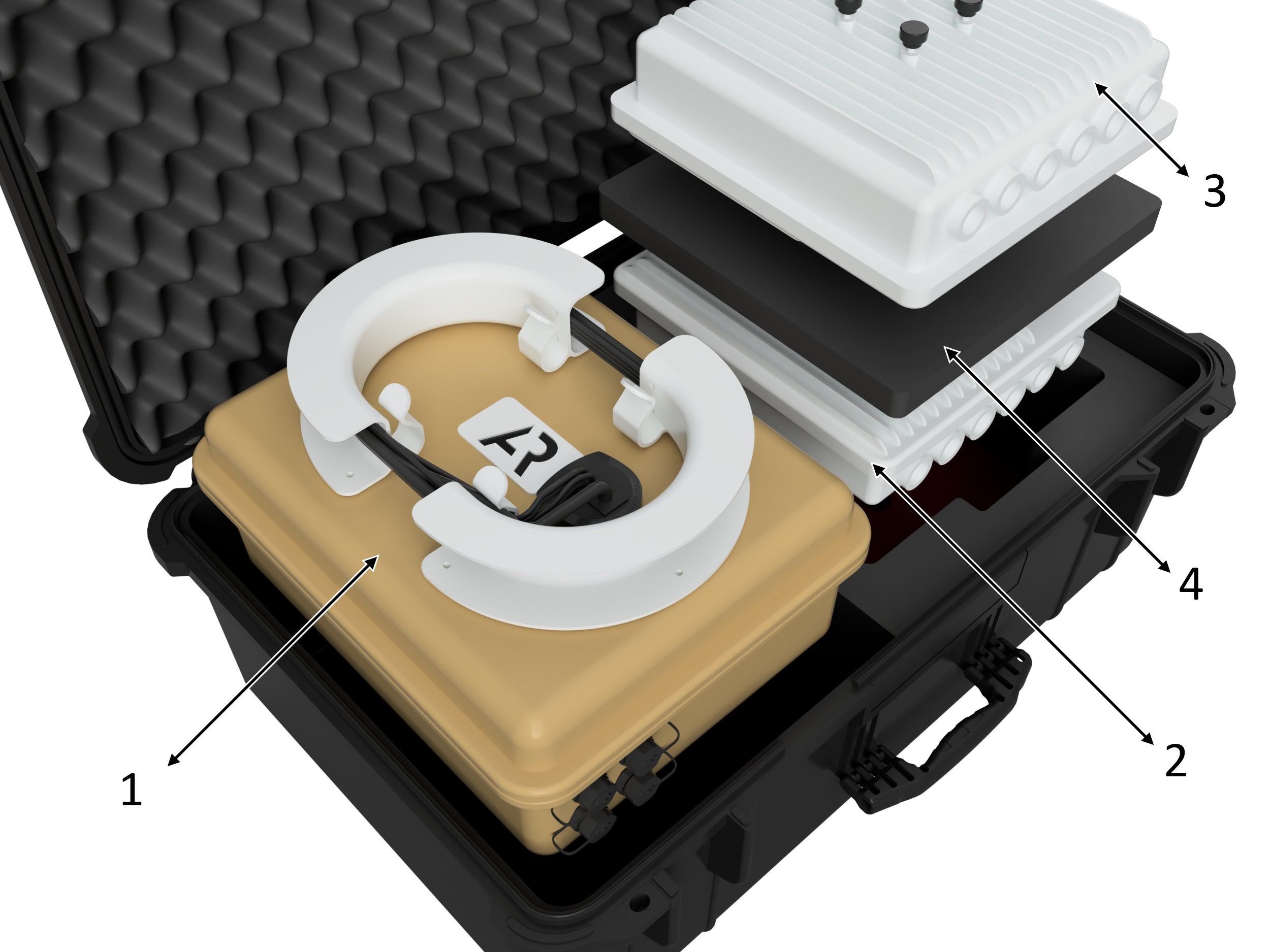
Case 1 breakdown
- Tracking camera (If used)Store the tracking camera with the ethernet connection facing upwards and the camera head laying flat as shown.
- Radar panel
- Radar panel arms
- SEN-ID/SEN-HUB bracket
- Cable clip
- Antenna 1
- Antenna 2
- GPS antenna
- ADS-B antenna
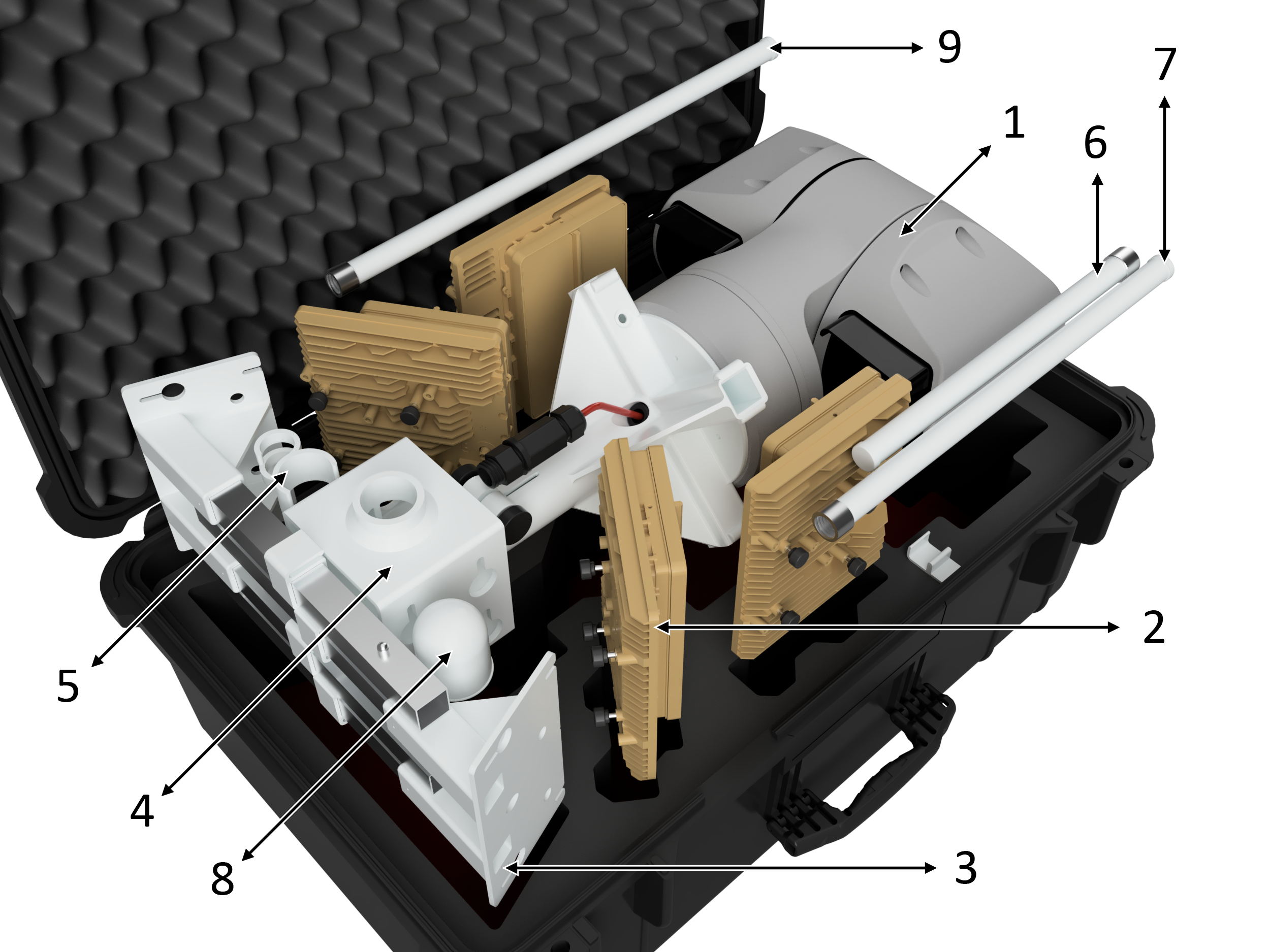
Case 2 breakdown
- NESTPower and radar cables store wrapped around the spool.
- SEN-IDStore unit with thumbscrews facing down.
- SEN-HUB (If tracking camera is used)Store unit with thumbscrews facing up.
- Foam separatorPlace foam separator between the two units.
Set Up | Tripod Hardware
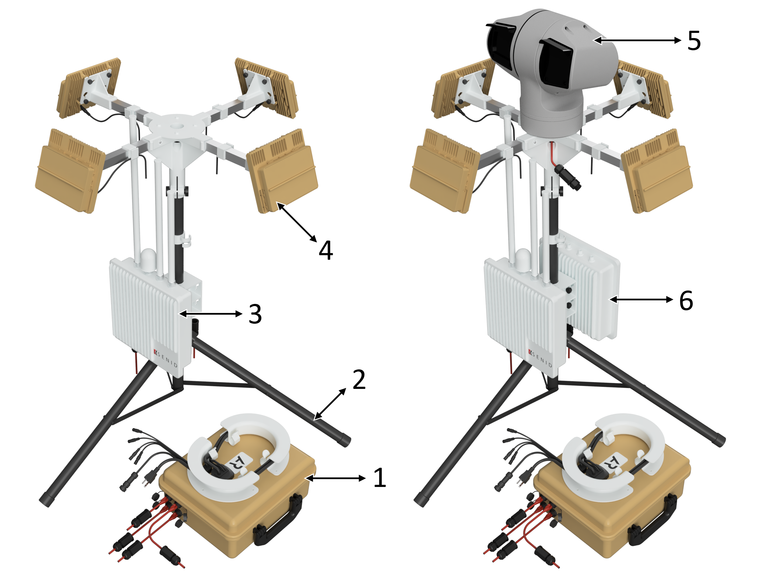
Exploded View
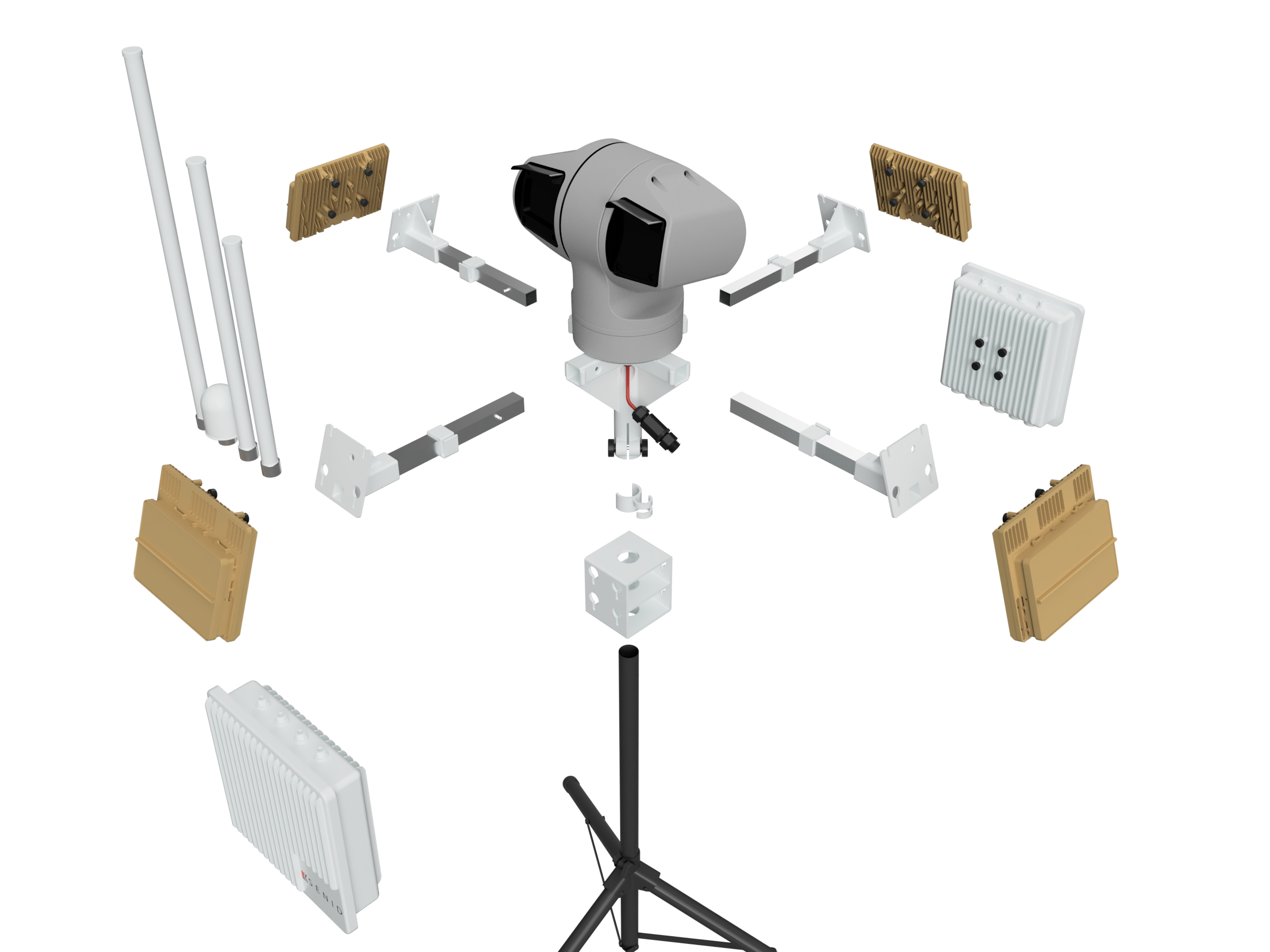
- Tripod
- Sensor bracket
- Radar/camera bracket
- Radar panel arm
- Radar panel
- SEN-ID
- SEN-HUB
- Cable clip
- Antenna 1
- Antenna 2
- GPS antenna
- ADS-B antenna
Tracking Camera
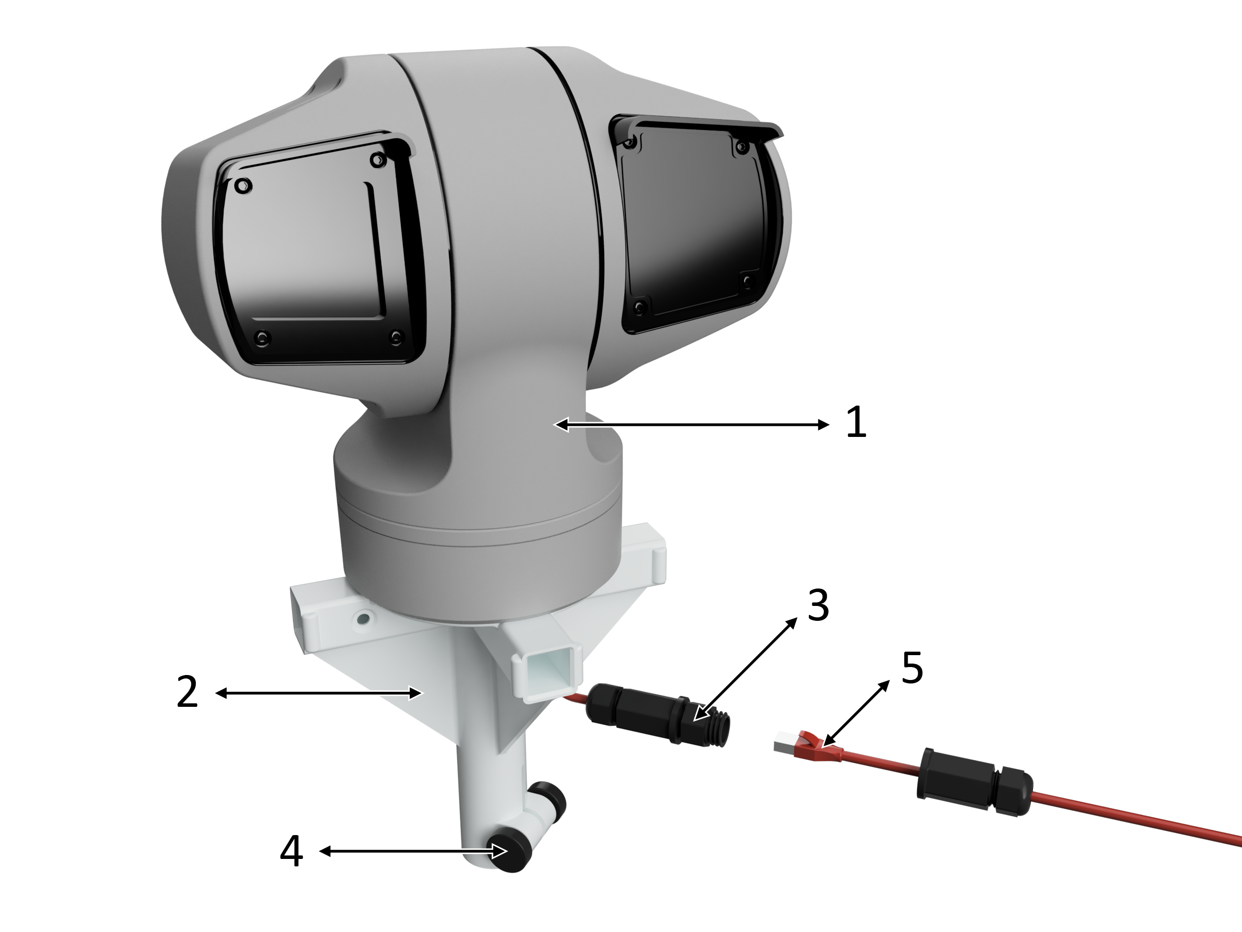
- Axis Communications Q6225-LE 2MP Outdoor PTZ Network Camera
- Radar/camera bracket
- Weatherproof camera ethernet connection
- Thumbscrew
- Ethernet cable from Nest
Echodyne | Echoguard Radar Panels
- Echoguard radar panelPlace thumbscrews in radar panel arm slots and tighten the thumbscrews
- Radar panel arm
- Radar panel cable
- Radar panel cable connectorConnector is keyed. Sleeve slides back for release
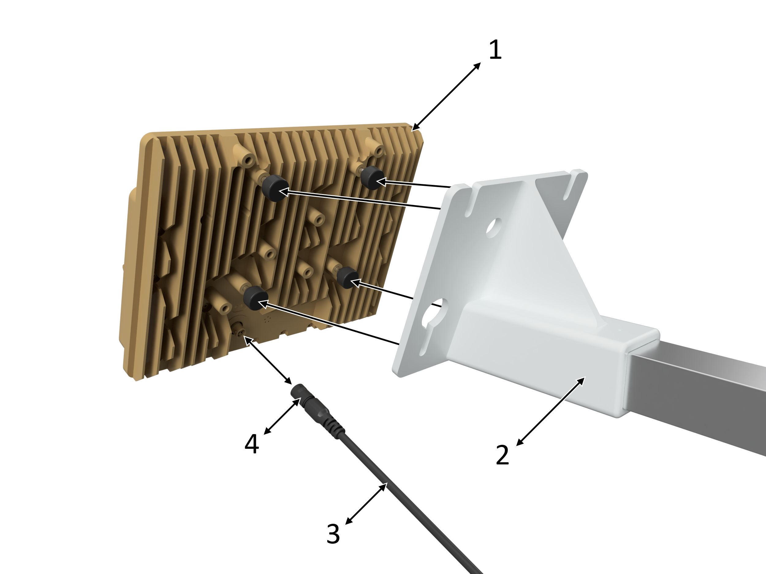
Set Up | SEN-ID/SEN-HUB
SEN-ID Antenna Installation
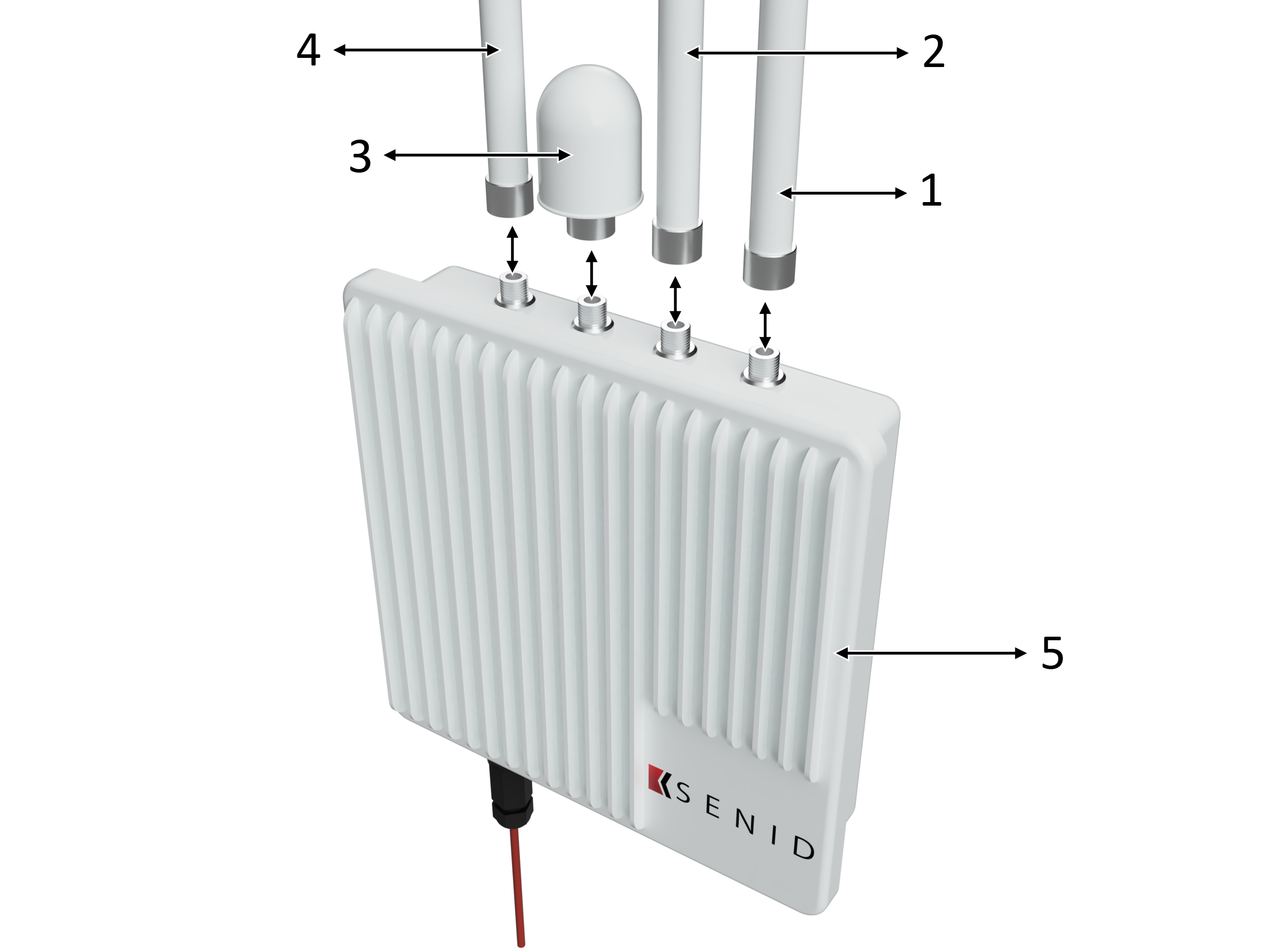
- Antenna 12 - 3 Ghz
- Antenna 23 -6 Ghz
- GPS antenna
- ADS-B antennaAutomatic Dependent Surveillance-Broadcast. Real-time, aircraft position, speeds and other data.
- SEN-ID unit
SEN-ID Cable Installation
- SEN-ID unit
- Ethernet cableConnect port A of SEN-ID to port 1 of NEST. Connect port A of SEN-ID to port D of SEN-HUB if using a tracking camera.
SEN-HUB Cable Installation (If tracking camera is used)
- SEN-HUB Unit
- SEN-HUB power cableThis cable comes from the spool on the NEST.
- Ethernet cableConnect port E of SEN-HUB to port 1 of NEST.
- Ethernet cableConnect port D of SEN-HUB to port A of SEN-ID.
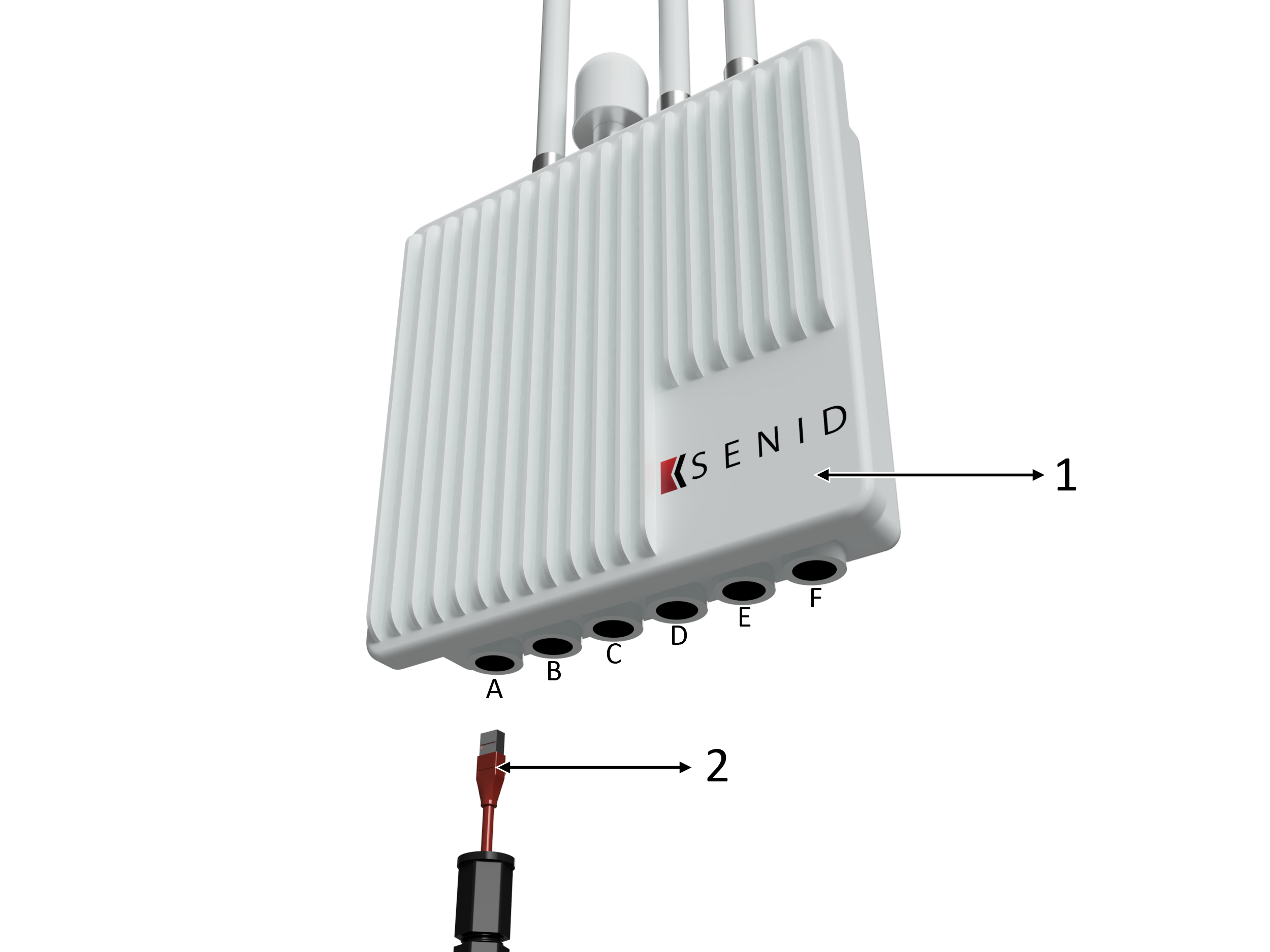
Set up | NEST
Ethernet Ports
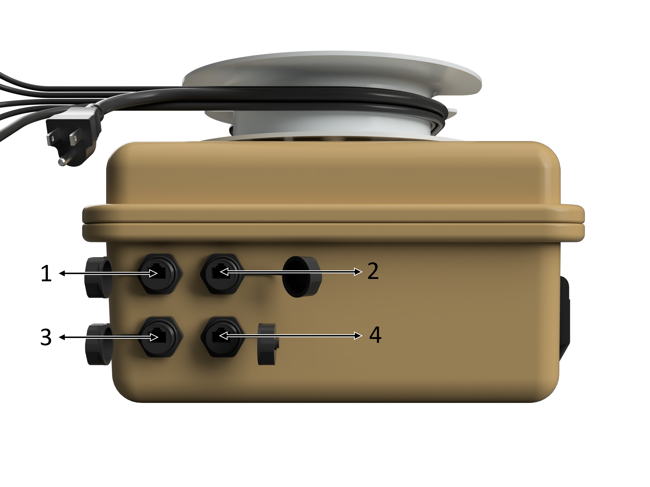
- Ethernet port 1Connect port 1 of NEST to port A of SEN-ID. If tracking camera is used, connect port 1 of NEST to port 3 of SEN-HUB.
- Ethernet port 2Internet connection.
- Ethernet port 3Connect to tracking camera.
- Ethernet port 4User connection (laptop).
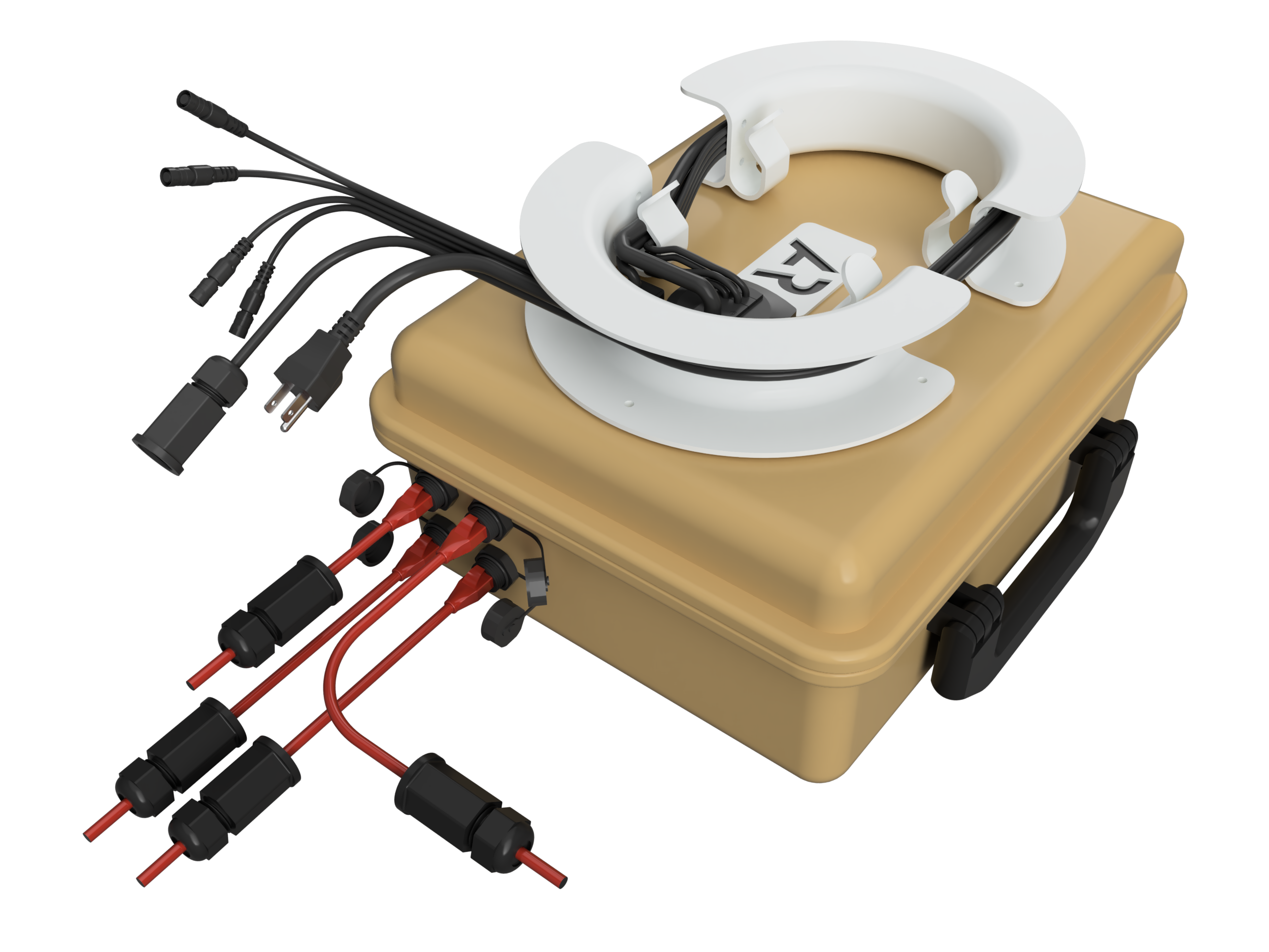
Cable Connections
- Ethernet port 1Connect port 1 of NEST to port A of SEN-ID. If tracking camera is used, connect port 1 of NEST to port 3 of SEN-HUB.
- Ethernet port 2Internet connection.
- Ethernet port 3Connect to tracking camera.
- Ethernet port 4User connection (laptop).
- NESTKESTREL support box houses all power and data equipment.
- 110v power
- Radar cablesAny cable can connect to any panel.
- SEN-HUB power cableConnects to port F on the SEN-HUB unit if a tracking camera is being used.
Operation | Detecting Targets with RF and SEN-AIR
SEN-AIR - Getting Started, Live Map
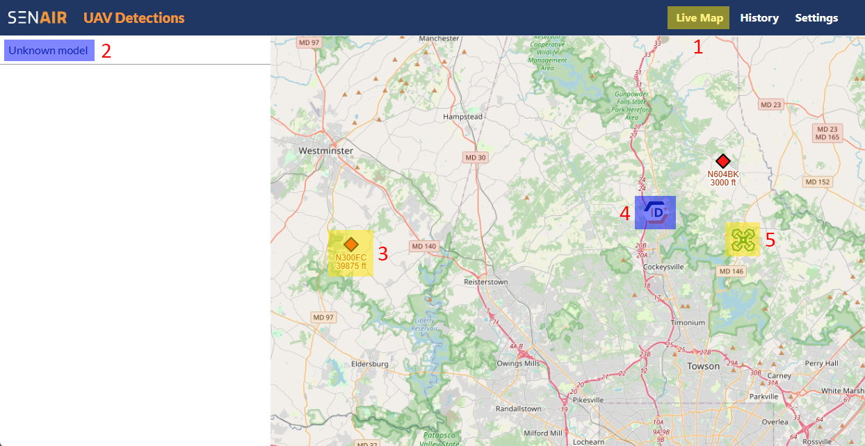
Navigate to your provided client URL (yourusername.stg-portal.senair.io). Enter your username and password.
- "Live Map" tabSelect the "Live Map" tab to see a live view of currently detected live targets.
- Detected Remote ID aircraftLive RF detected targets will be displayed in the left margin. Select a target to see information about that target.
- Detected ADS-B aircraft location
- SEN-ID unit location
- Detected Remote ID aircraft
SEN-AIR - Detected Targets
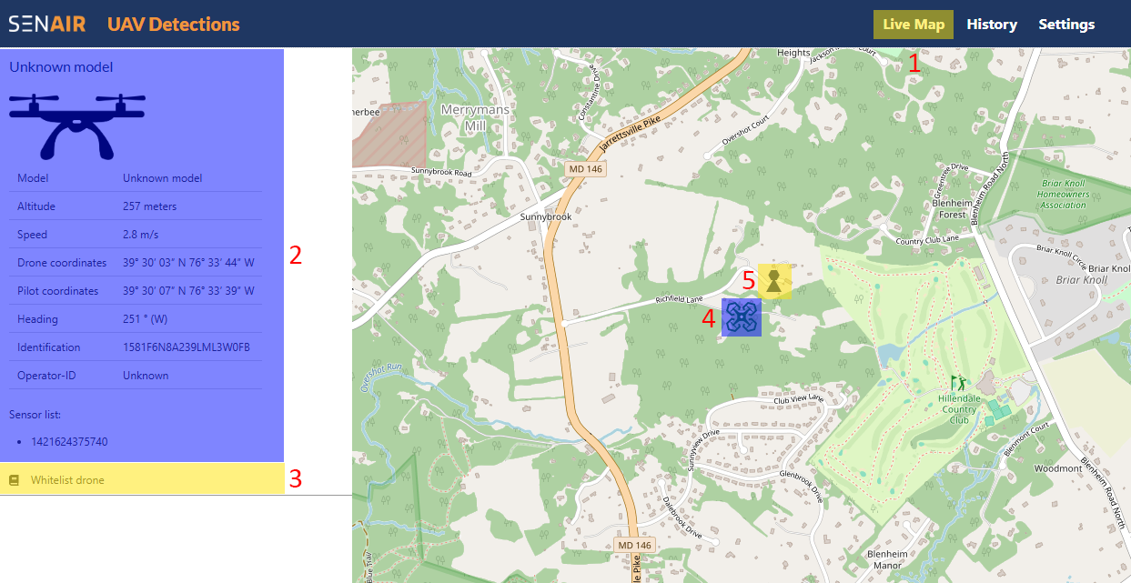
- "Live Map" tabSelect the "Live Map" tab to see a live view of currently detected live targets.
- Detected Remote ID aircraftSelect a target to display all available information about that target, including the operator location.
- "Whitelist drone" tabSelect the "Whitelist drone" tab to add the currently selected aircraft to the whitelist. This will cuase the aircraft icon to appear green while preventing the aircraft from setting off alerts.
- Detected Remote ID aircraft location
- Live operator location
SEN-AIR - Detection History
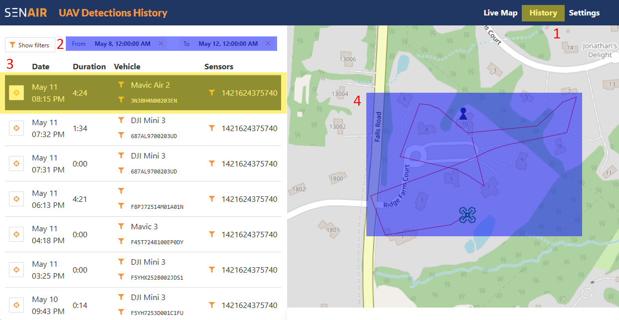
The system allows a user to view a history of recorded detections.
- "Live Map" tabSelect the "History" tab to see all recorded flight detections.
- Selected date rangeDate range fields allow you to see recorded flights within a certain range of time.
- Individual detected flight infoIndividual flights are displayed in the right side margin. Select an individual flight to see aircraft and operator location for that flight.
- Individual detected flight visual representationAircraft and operator location is displayed on the map.
SEN-AIR - History Filters
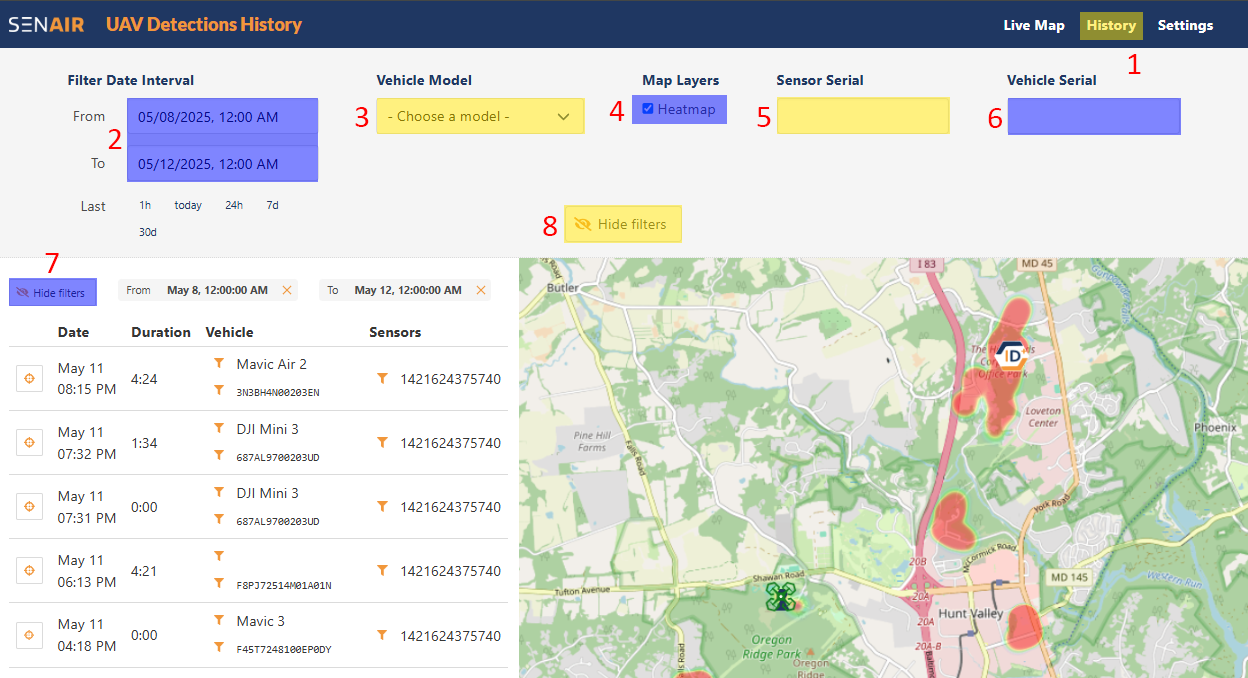
Detected flight history can be filtered out by time, aircraft type and serial number.
A user can also opt to have a heatmap displayed to indicate flight activity during the specified parameters.
- "Live Map" tabSelect the "History" tab to see all recorded flight detections.
- Date rangeUse these two fields to filter out detections by date and time of day.
- Model typeFilter flights by aircraft type.
- Heat map toggleSelect or deselect to create a heatmap of flights based off the filter criteria.
- Sensor serial number filterUse this field to filter detections by SEN-ID sensor. This is useful when operating multiple sensors.
- Aircraft serial number filterFilter detected flights by aircraft serial number. This is useful when the user wants to see all flights from a particular aircraft.
- "Hide/Show" filters toggleeexwwxwHide or display filter options.
- "Hide filters" tab
SEN-AIR - Settings
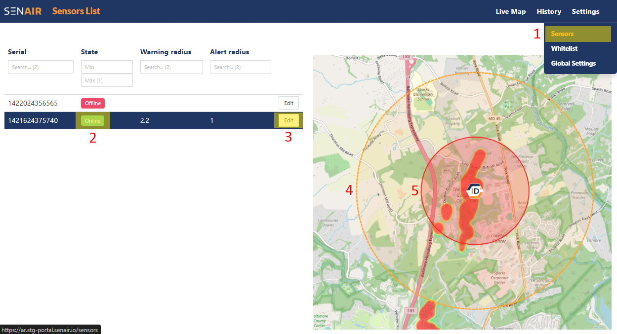
The "Sensors" panel displays all available sensors, indicates their operating status and allows the user to alter warning and alert radius settings.
- "History > Sensors" tabSelect the "History > Sensors" tab to see all sensors being operated by the KESTREL system.
- Sensor "online/offline" indicator This row displays your sensor serial number and indicates if the sensor is online or offline.
- "Edit sensor" tabSelect this tab to change warning and alert radius settings.
SEN-AIR - Setting Alert and Warning Radii
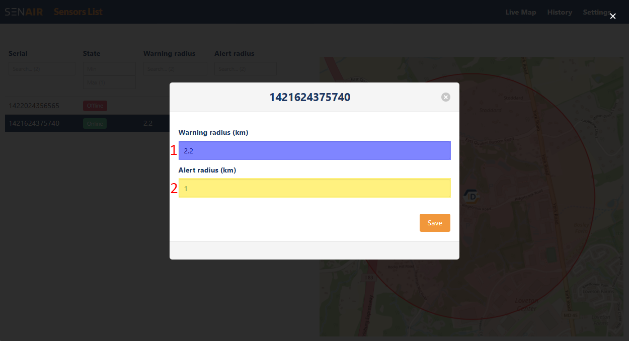
"Warning" and "Alert" radii give two different levels for awareness of aircraft in the area of interest.
"Warning" is intended to be used to alert the user when an aircraft is detected in the surrounding area.
"Alert" is intended to warn the user of aircraft considered to pose a potential hazard due to their close range.
- Warning radius valueEnter a value in km here for the "warning" radius. Set to 0 to disable.
- Alert radius valueEnter a value in km here for the "alert" radius. Set to 0 to disable.
Operation | Detecting Targets with Radar and RadarUI
RadarUI - Getting Started
This is intended as a quick start guide. Download the complete RadarUI guide here.
Install RadarUI by downloading and unzipping this folder: radarUI
Navigate to: radarUI > bin.
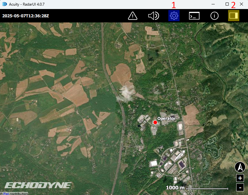
Open the radarui application.
- ConfigurationOpen this tab to access the Configuration panel.
- SettingsOpen this tab to access the Settings and start the panels.
Configuration | Radar Table
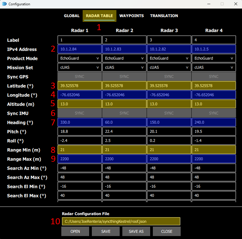
In this step the user will enter values that determine the location and orientation of the KESTREL system.
Navigate to: Configuration > Radar Table
- Radar tableSelect Configuration > Radar Table to access the Radar Table values.
- Panel IP addressesEnter the radar panel IP addresses provided to you in the IPv4 Adress row. Take notice of every IP address assigned to each radar panel (1-4).
- Panel latitude coordinatesEnter the latitude for each panel. This is latitude of the KESTREL system itself, and should be the same value for each panel.
- Panel longitude coordinatesEnter the longitude for each panel. This is longitude of the KESTREL system itself, and should be the same value for each panel.
- Panel altitudeEnter the AGL altitude for each panel. This is altitude of the KESTREL system panels, and should be the same value for each panel.
- Panel sync buttons * Come back and complete this step when the panels are connected, but not started. Click on the "SYNC" link for each radar panel in each column. This will automatically update the pitch and roll values for each panel. With the tripod level, pitch should be close 20 degrees and roll should be close to zero. A few degrees in either direction is acceptable.
- Panel headingsIn the heading row, enter a heading value (0-360) for eack radar panel. Use a compass to determine the correct heading for each panel. The radar panel arms are all positioned 90 degrees from each other, so extrapolating panel headings from a single good reading should be simple. Panels do not have to be aligned in any particular direction.
- Panel minimum detection rangesEnter a minimum range you wish to detect targets at. The minimum accepted value is 21 meters which is the recommended value. This results in a 20 meter dead spot where targets can not be detected which is normal.
- Panel maximum detection rangesEnter a maximum range you wish to detect targets at. The maximum practical value is 6000 meters.
- Radar configuration file locationThis is the location of the .json file where the radar table values will be stored. You may select the "OPEN" button to navigate to and load an alternate file.
Configuration | Waypoints
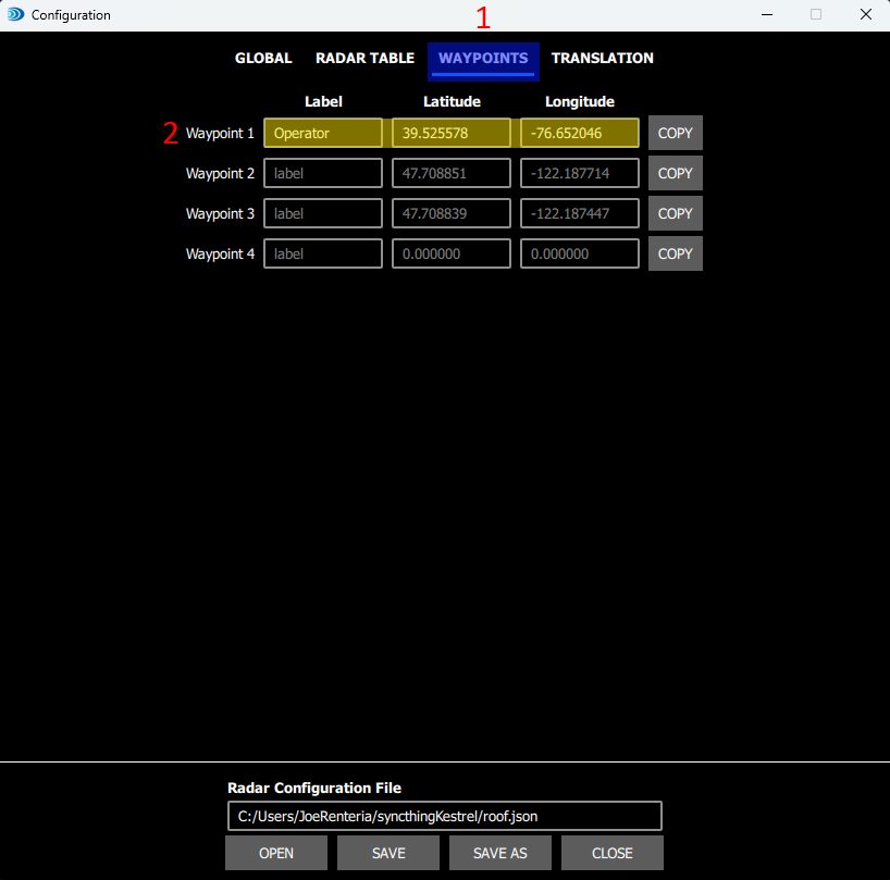
Navigate to: Configuration > Waypoints
- Waypoint configurationSelect the "Waypoints" tab to create a waypoint within the RadarUI GUI. This will serve as your operator location, represented by a red dot on the GUI.
- Operator label and coordinatesIn the "Label" field for "Waypoint 1" enter "Operator". Then click on the "COPY" button. This will add the Lat/Long values from Radar Panel 1 to Waypoint 1.
Settings | Display | Track Filtering
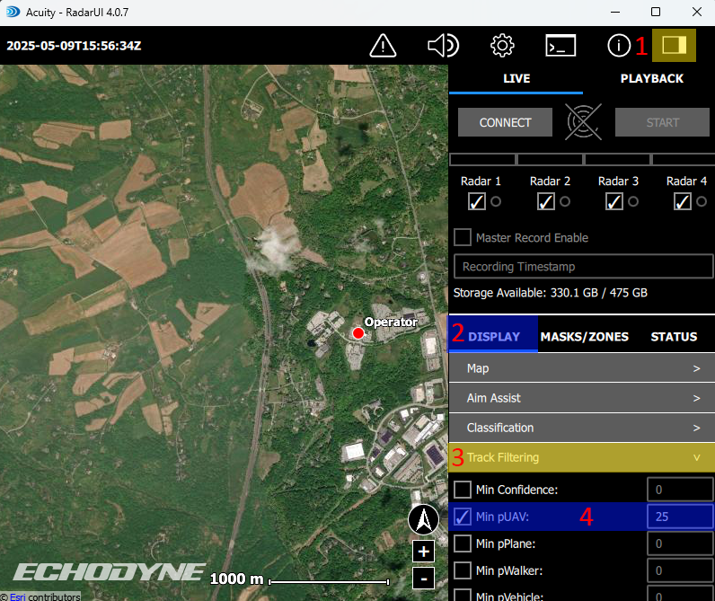
Navigate to: Settings > Display > Track Filtering
- Settings Tab
- Display Tab
- Track Filtering Tab
- Minimum UAV Confidence Adjust minimum UAV confidence level as desired. 25% is a good starting point.
Settings | Masks/Zones | Global
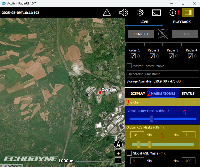
Navigate to: Settings > Masks/Zones > Global
- Settings Tab
- Masks/Zones Tab
- Global Tab
- Global Clutter Mask Width Slider Adjust the Global Clutter Mask Width slider as desired. 3 is a good starting point.
- Global RCS Masks Slider Adjust the Global RCS Masks slider as desired, -34 to -7 (dBsm) is a good starting range for small to medium UAS.
Settings | Connecting to/Starting the Radar Panels
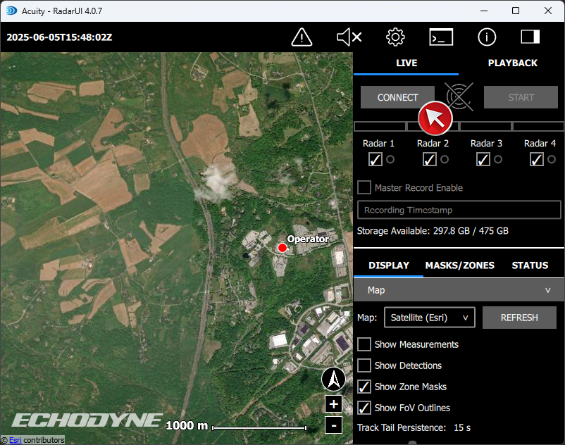
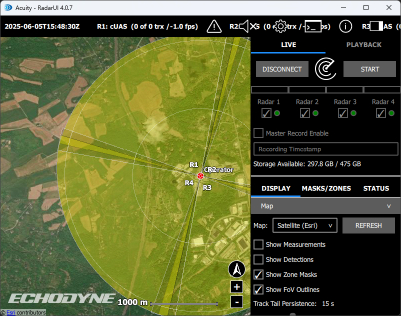
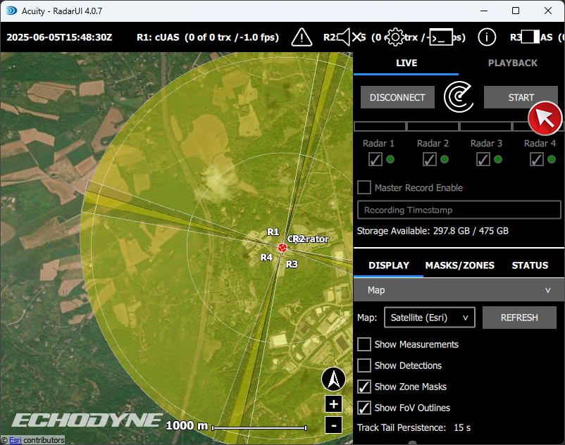
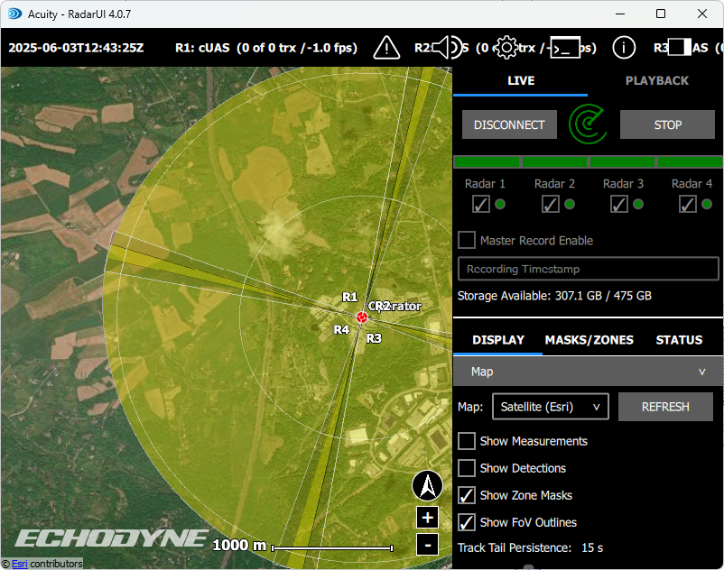


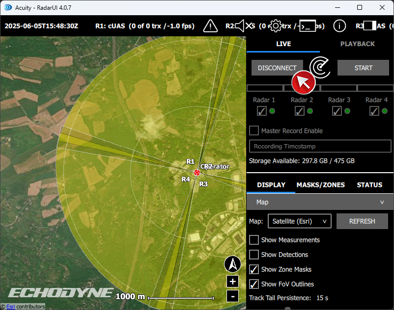
Navigate to: Settings Tab
- Settings Tab
- Connect/Disconnect Button Connect to the radar panels by selecting the start button.
- Start/Stop Button Select the start button to start the radar panels.
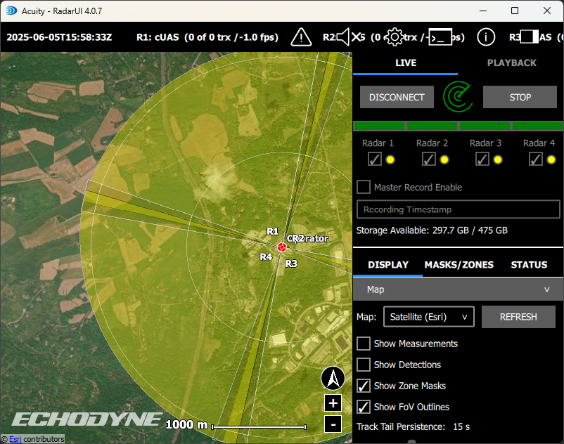
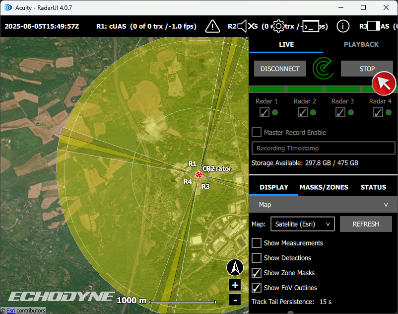
Tracking Targets
- Settings Tab
- Track Tracks determined to be UAS will appear as red on the radarUI screen
- Track Class Legend Track types are categorized by color. See Track legend.